Programming board
To start programming board lets first learn about board; On board we have Atmega328 MCU with Arduino uno bootloader , and ESP12e wifi module . Both of them must be programmed via Arduino IDE. So Atmega328 is used to pick up all information from sensors and then send it to esp12 via serial protocol.
- Esp12 is used to pick up informations from atmega328 mcu and send it to server.
- On atmega328 we use a Software serial to communicate with ESP12.
- On ESP12 we use Hardware Serial to communicate with atmega328 , note here is to be care when uploading code to esp12 if you have code on atmega328 that constantly sending something via software serial your code to esp cant be uploaded , so to fix this you need to change code in atmega "comment all serial print lines" and then upload code to esp12.
- For this board you will need preloaded arduino bootloader on atmega chip becouse pins are not put on board becouse of sizing board.
Ok to start programming make sure to solder atmega328 with preloaded arduino bootloader when you make that take look on the board for these pins;

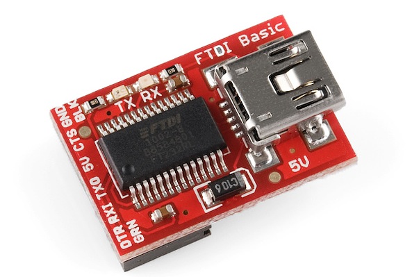
You will notice you have a vcc , gnd , dtr , rx , tx . For now you must buy FTDI chip looks like one from the link it must have a DTR pin its very important.
- Connect it like this :
- Device---------FTDI
- Gnd------------Gnd
- vcc------------5v
- tx-------------rx
- rx-------------tx
- dtr------------dtr
When you have connected it like this you can connect you FTDI to laptop and in Arduino IDE choose Arduino uno , your port and upload some code to test it. If it succesefuly upload the code your chip is working.
To programm ESP12 first make sure that Atmega328 chip is not sending any data via software serial to ESP12 , and you need to prepare you Arduino IDE for esp so watch this tutorials for implelenting ESP in Arduino IDE (Tutorial1, Tutorial2).
So for wiring you need FTDI and little bit known of soldering so first as we mentioned you have a pins on board like this;
From this pin we will use only a pins VCC,GND for this pins get 5v to vcc and gnd to gnd on FTDI. First read this tutorial to be more friendly with ESP12 just read it. So to put esp12 in programming mode we need to short jumper or to press and hold button

So first turn off power from pcb then short jumper or hold button and then power up device and the esp12 is in programming mode so then solder two wires to this pins;
Connect it to FTDI like this ;
- ESP12-------FTDI
- rx----------tx
- tx----------rx
- vcc---------5v
- gnd---------gnd
Then you can upload code to ESP12 if you see done uploading all is ok with your device.
So which code to upload on ATMEGA328 and ESP12:
- For Atmega328 upload this code
- For ESP12 upload this code